📢 Fresh Content: PLC Troubleshooting Tips That Work Across Any Platform | Click to read on PLCBlog!
Explore Our Blog
Blog Posts
In-depth PLC programming and industrial-automation guides — ladder logic, timers, SCADA, HMI and communication, plus the practical know-how the field runs on.
 Featured
PLC Panel Electrical Noise: Causes and Fixes
Electrical noise in PLC panels causes phantom inputs, drifting analog readings and comm errors. Learn the real causes and practical fixes, wiring changes included.
Aug 4, 2026 · 10 min read
Read article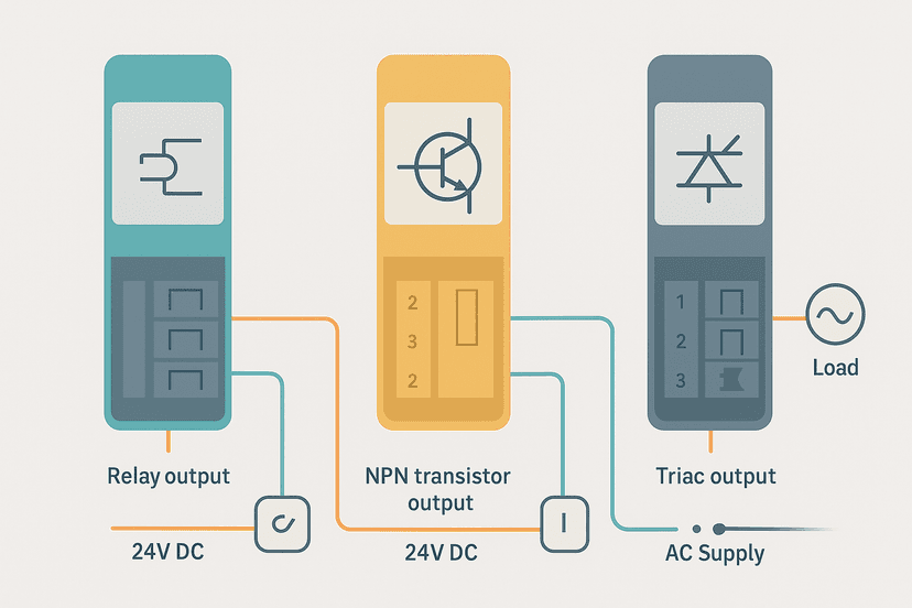
PLC Output Wiring: Relay, Transistor and Triac
Relay, transistor and triac PLC outputs wire differently and fail differently. Here is exactly how to connect each type and avoid the mistakes that kill modules.
Aug 4, 2026 · 10 min read
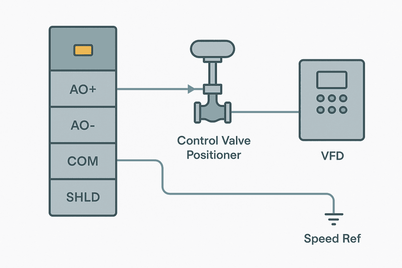
PLC Analog Output Wiring: 4-20 mA and 0-10 V
Step-by-step guide to wiring PLC analog outputs: 4-20 mA current loops and 0-10 V voltage signals, with real wiring gotchas, load limits and field-verified tips.
Aug 3, 2026 · 11 min read
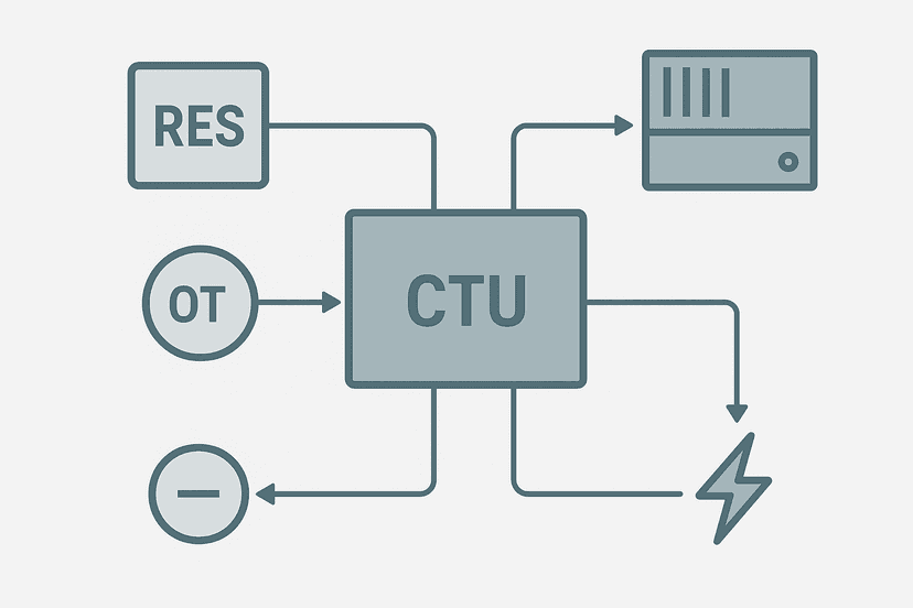
PLC Counter Reset: 4 Methods and When to Use Each
Resetting a PLC counter sounds simple until it bites you mid-batch. This guide covers every reset method, when each one is right, and the gotchas that cause missed counts.
Aug 3, 2026 · 8 min read
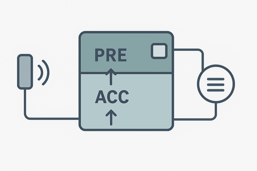
PLC Counter Preset vs Accumulator: What Each Does
The preset and accumulator in a PLC counter do very different jobs. This guide explains each one, how they interact, and the real-world gotchas you need to know.
Aug 3, 2026 · 8 min read
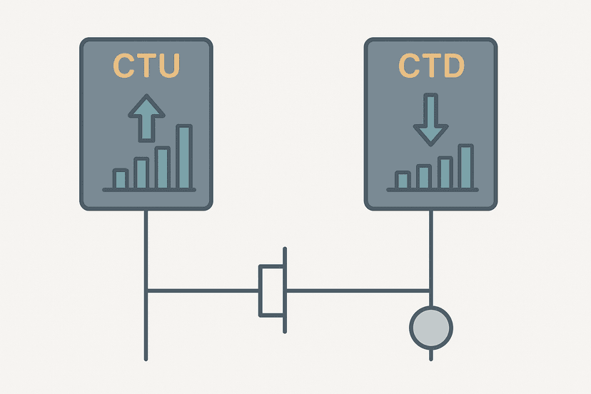
CTU vs CTD: PLC Counter Instructions Compared
CTU counts up from zero; CTD counts down from a preset. Learn when to use each, how they differ across platforms, and how to wire both into working ladder logic.
Aug 2, 2026 · 9 min read
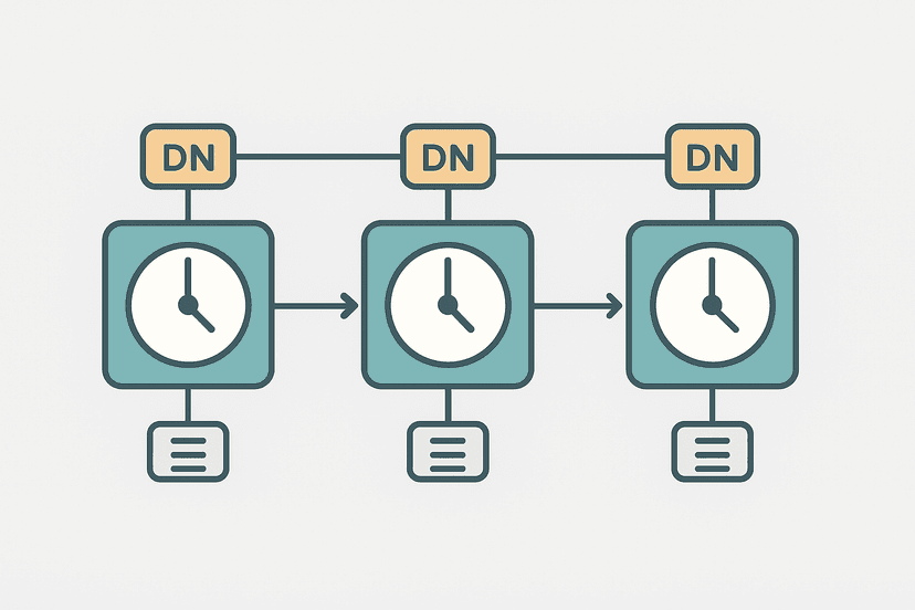
Cascading PLC Timers: Chain TON Logic Right
Learn how to cascade TON timers in PLC ladder logic to build reliable multi-step timed sequences. Real examples, common mistakes, and field-tested patterns.
Aug 2, 2026 · 7 min read